Beam Approach Beacon System

Sources and Corrections
www.rafmuseum.org.uk www.airfieldresearchgroup.org.uk Wikkipedia
Vintage and military amature radio society VAMARS
Public information is limited regarding beam approach - the author has interpreted these findings from information from the above main sources (as well as others) and investigating the remaining ground features at the former air station - the author invites any corrections or input from page visitors - many thanks
During December 1945 No.1528 Radio Aids Training Flight with Airspeed Oxfords trained at RAF Blakehill, using the station’s beam approach for training.
The Beam Approach Beacon System – or ‘BABS’ – was a homing device used to help pilots land in poor visibility. Radio beacons on the airfield transmitted signals, which were picked up by aircraft on their approach to land.
Lucero was the name given to the equipment placed at the end of the runway. It picked up the height to slope (H2S) pulses from an aircraft and returned them into 'left and right' dots and dashes, enabling the aircraft to find the centre line. Lucero was designed as an interrogation device ‘asking’ the Rebecca pulse generated by the aircraft to provide a signal it could decode.
‘Lucero’ took its name from Diego Rodriguez Lucero, an infamous member of the Spanish Inquisition.
The Main Beacon at the end of the runway transmitted a signal in the form of a narrow beam. When the pilot was lined up correctly on this beam the signal received was steady and he knew he was heading straight towards the runway. If he was too far to the left or right, the signal received was a stream of dots or dashes and he corrected his course until the signal changed to a steady pulse.
When the aircraft crossed the Outer and Inner Marker Beacons the pilot also detected their distinctive signals, which told him how far he was from the point of touch-down. He used this information to check his rate of descent until the ground came into view and he could make a safe visual landing.
'A' Type Airfields like Blakehill were intended to have two fixed systems at the end of the two most used runways. At RAF Blakehill, the remains on the ground would suggest runways 2 ,(fairly obvious as this was the main 2000 yard runway) and number 3.
These were switched on from the control tower. To save on installation time and underground cabling the remaining four runway ends were serviced by portable or semi-portable systems.
The semi portable system used a fixed pre-aligned aerial system but the electronics and power supplies were housed in a small van.
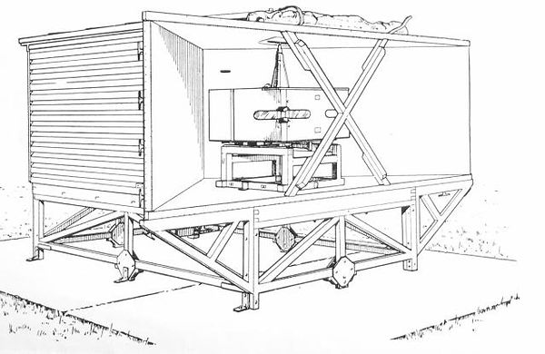
Above - Diagram of Fixed Luceo Receiver note 8 legged metal chassis mount

Above - Luceo Plinth SW end of Runway #2 - 8 socket holes in concrete where metal chassis fitted - Below - original cabling in situ

Below - Equipment plinth NE end of Runway #2 - with metal ladder remaining
The mobile version of Lucero apparently took a long time to set up.
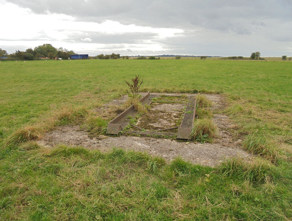
There is evidence at RAF Blakehill that a vehicle sat on a steel ramp cradle, bolted firmly to the concrete base at the north eastern end of Runway #1
It is understood that then a cable was connected to a small fixed antenna exactly on the runway centre line or vehicle.
The remains of the steel ramp cradle looks to be set on a perfect alignment with this reserve runway, which like most of the Blakehill air station, has sadly been lost.
Below - the fixed vehicle ramp in situ at the NE end of runway #1 on the lead in to the long demolished runway


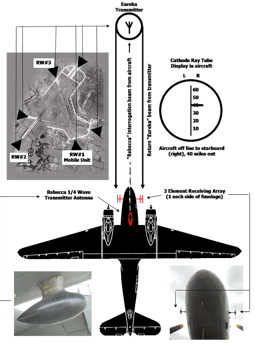
The airborne Rebecca set transmitted a series of encoded 300 Watt short pulses using a quarter-wave vertical aerial which was usually installed immediately under the nose of the aircraft – shown here on a C47 Dakota.
The companion "Eureka" receiver was positioned on the ground at the drop or landing site from where a 12 W output transponder was triggered by the Rebecca signal to send a return signal to the aircraft on a separate frequency.

The Rebecca set in the aircraft measured the time lag between its own transmitted pulse and that received from the Eureka ground transponder to provide distance to target information on a CRT display with a vertical line calibrated in miles and varied in range by operator switch selection as the aircraft closed on the target location. A directional two element Yagi receive aerial was fitted to each side of the aircraft nose and the signals from each were displayed as lobes to the left and right hand side of the vertical display on the CRT, intersecting the vertical line display at the indicated calibration distance of the Eureka beacon from the aircraft. If the two side lobes were equal the aircraft was on a direct heading to the target, while an unequal left/right lobe display informed the pilot to change his heading by turning the aircraft in the direction of the larger lobe until lobe equilibrium was achieved.
Early airborne tests of Rebecca had found that the received signal from Eureka could be partially modulated by the aircraft propellers causing range errors and this was overcome by mounting the two aerials on the aircraft nose rather than on the outer underwings where, theoretically, they would have provided better heading discrimination.
Operationally, the Rebecca/Eureka homing system worked at up to 100 miles distance and could achieve an accuracy of 200 yards on its approach. From the pilot’s point of view, this was an excellent system